
Project Ares: Part II – Putting it together
Sharing the experience of building a home NAS/VM server.
This part describes building the machine, testing and measurements.
1. The hardware configuration
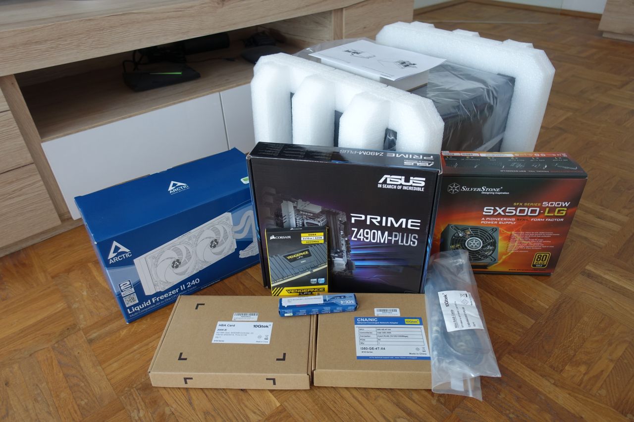
To reiterate the final HW configuration as described in the previous part:
| Item | Model | Remarks |
|---|---|---|
|
Case |
|
|
|
Power Supply |
|
|
|
CPU |
|
|
|
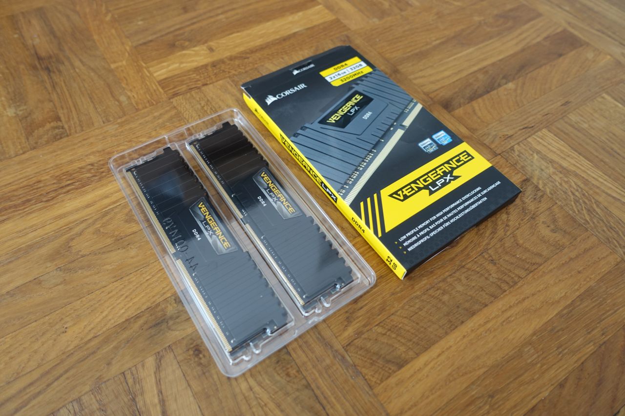
RAM |
|
|
|
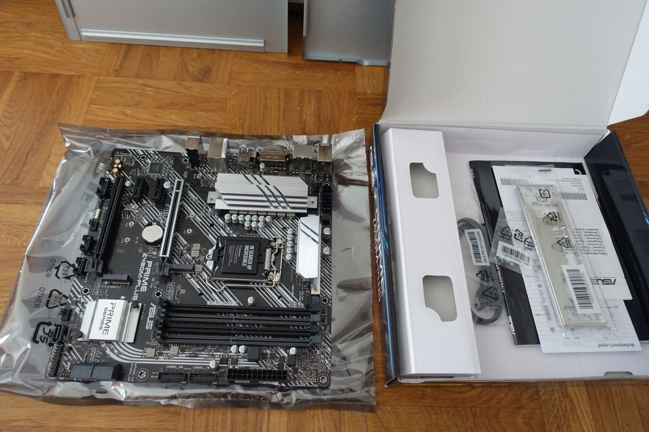
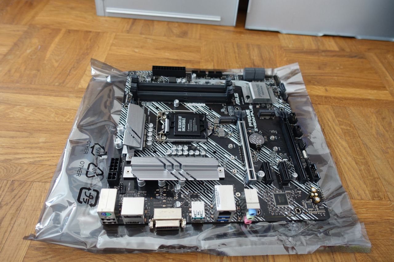
Motherboard |
|
|
|
CPU Cooler |
|
|
|
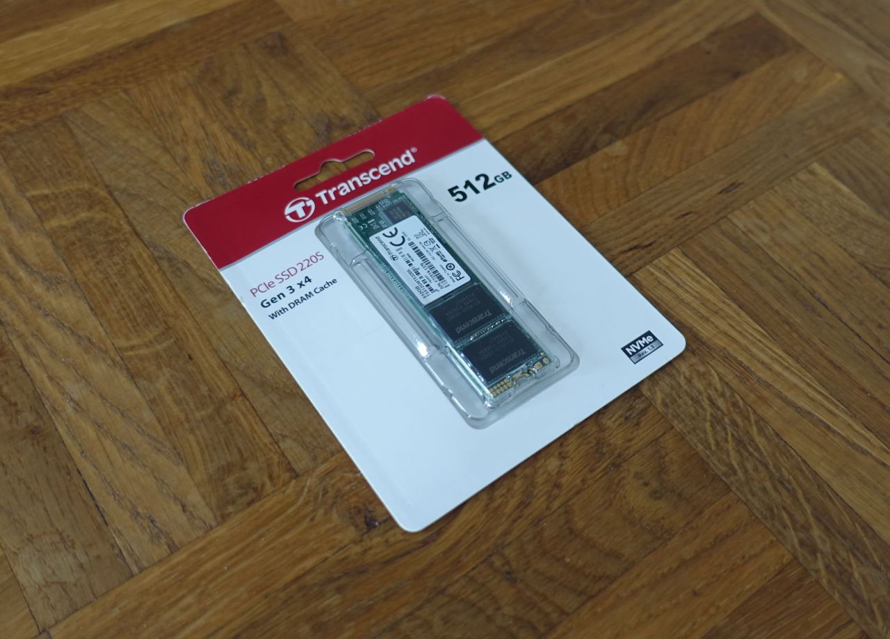
System SSD |
|
|
|
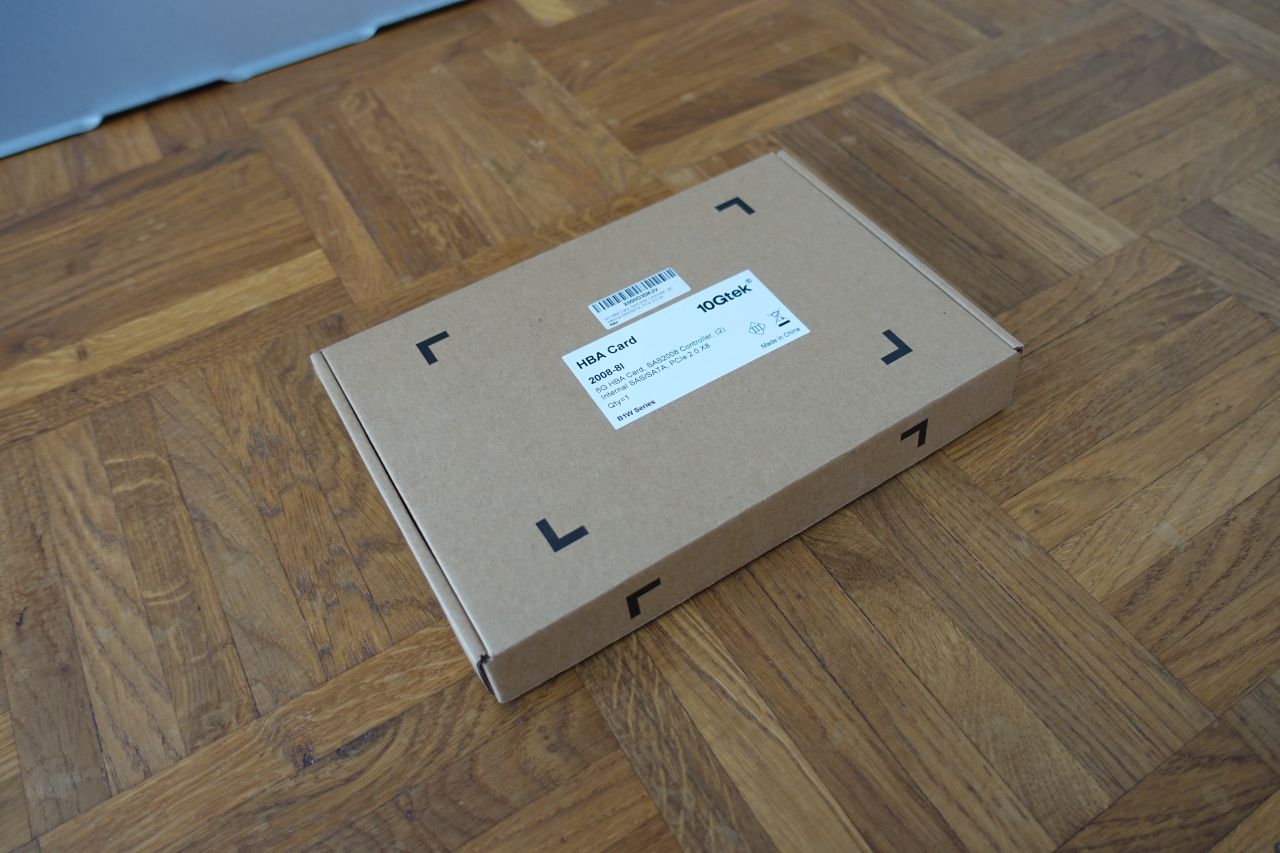
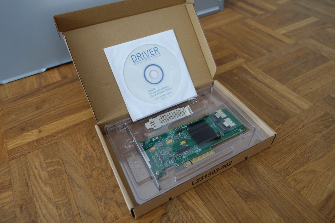
HBA Card |
|
|
|
HBA Cables |
||
|
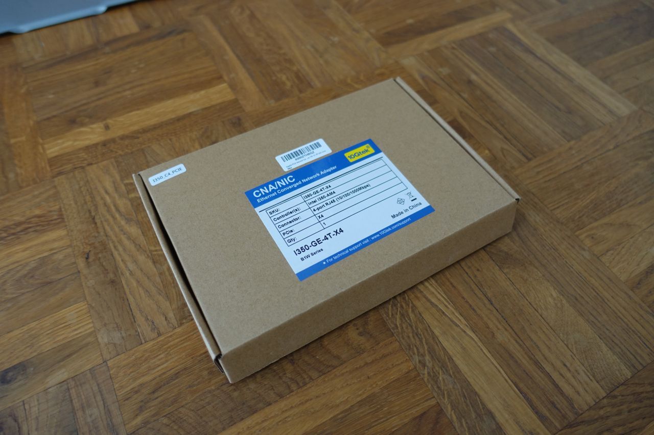
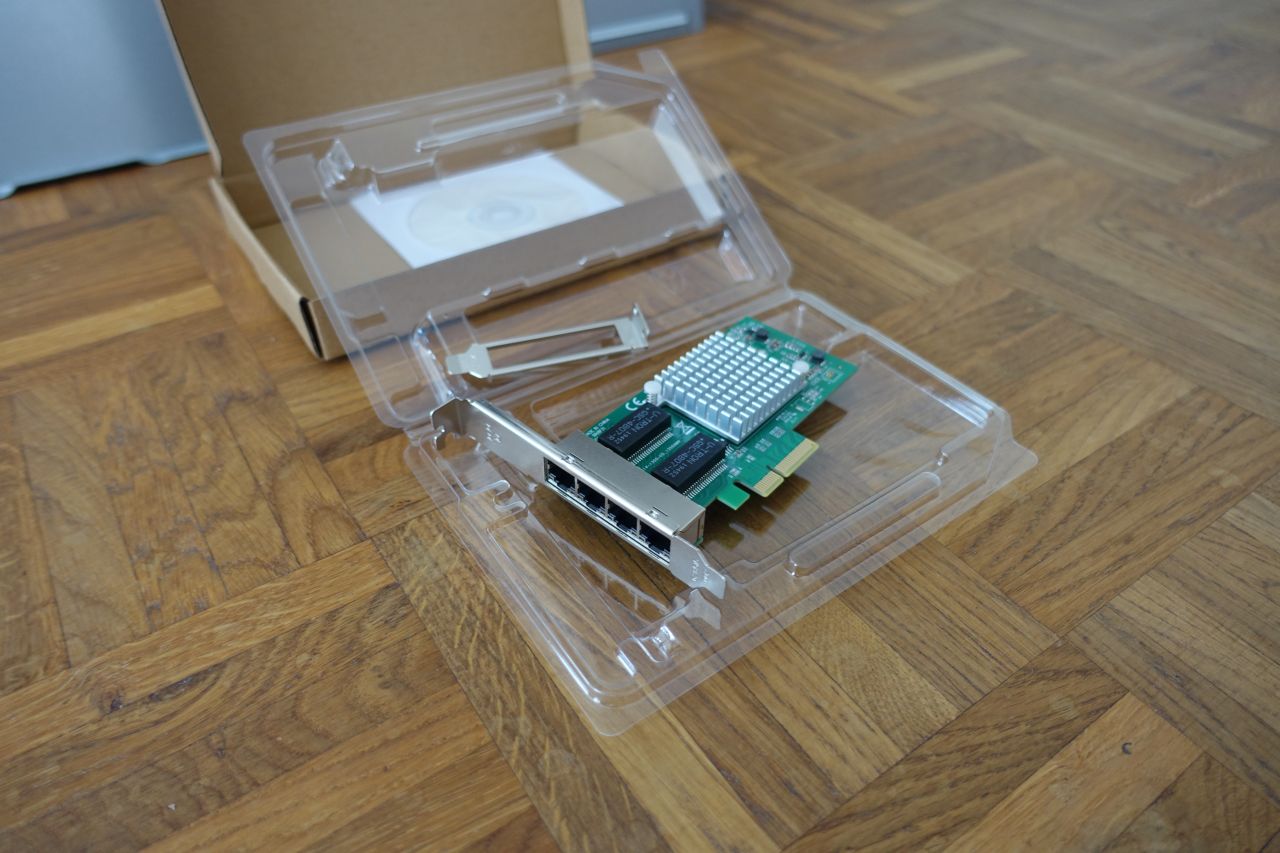
Network Card |
|
|
|
Ventilators |
|
|
|
2. Composing the NAS
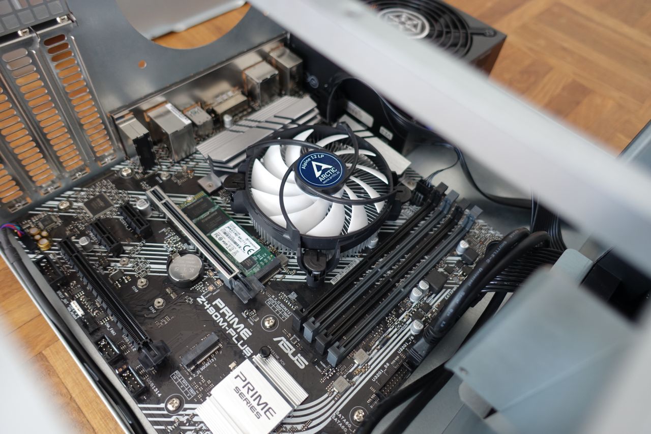
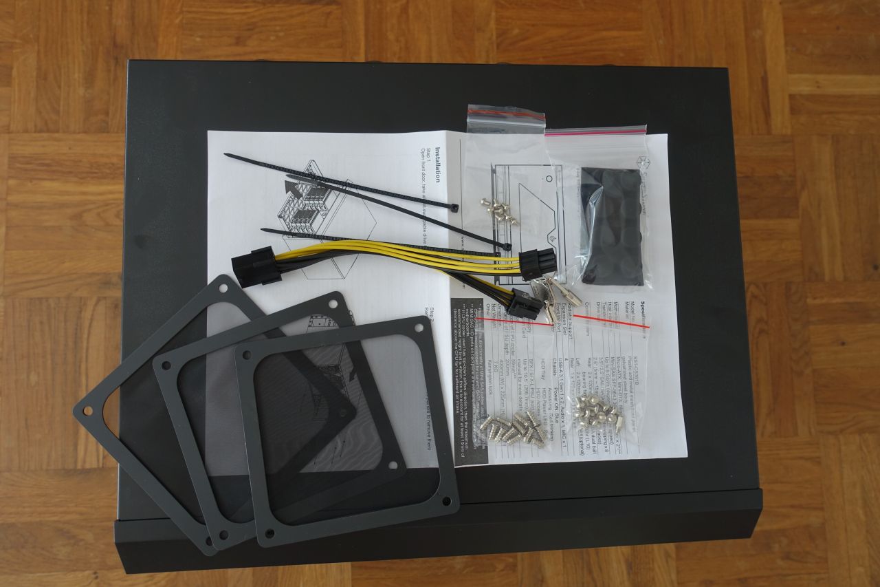
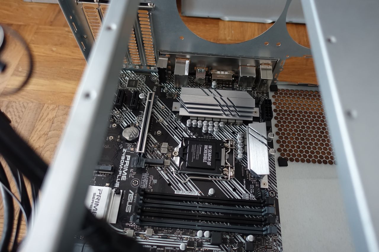
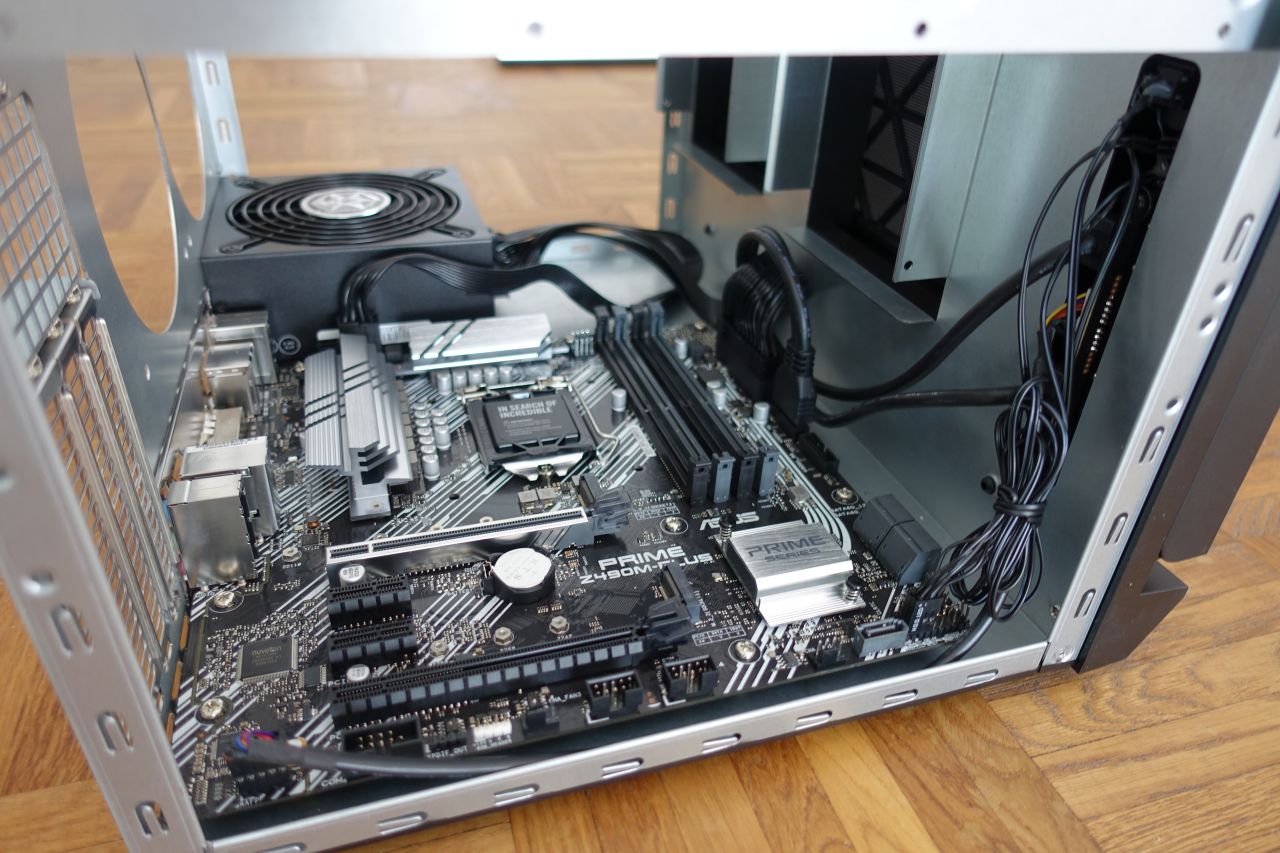
After all the basic parts finally arrived, I could start putting the NAS server together.
You can still notice the ARCTIC Liquid Freezer II 240 water cooling system in the picture. I initially planned to use it to improve the CPU temperatures, but unfortunately it didn’t fit in between the CPU socket and the HDD cage, so I was returning it and just used an air cooler (the CPU block itself would fit, but because of the pipes going up they collided with the HDD cage).
CAUTION: Beware the electricity! (both the line power and the static electricity)
When trying to build a new PC from parts, there are some general safety concerns and guidance:
- Never touch or change any parts while the the device is under power: First there is still a slight risk of electrocuting yourself (although not that big as all the parts except for the power supply are low voltage), but there is also a significant risk of damaging the parts when fiddling with them while powered.
When changing anything inside the PC, always switch off the power source, disconnect the power plug and wait for some time (at least 30sec recommended, there usually are some strong capacitors inside the power supply). - Static electricity: The electronic devices are not that delicate these days, but if you’re not careful enough and manage to get a very high static charge, you can still damage them - especially the more sensitive parts like the CPU and RAM modules. This can happen e.g. when slipping the foot over a carpet, wearing a thick woolen sweater etc. (you can eventually manage to get very high charges, reportedly up to 20-35 000 volts!)
I usually don’t go as far as to wear an antistatic strap, but before touching any devices I do often touch some grounded surface first (like a central heating radiator, the wall plug ground pin, the case of another connected PC etc.).
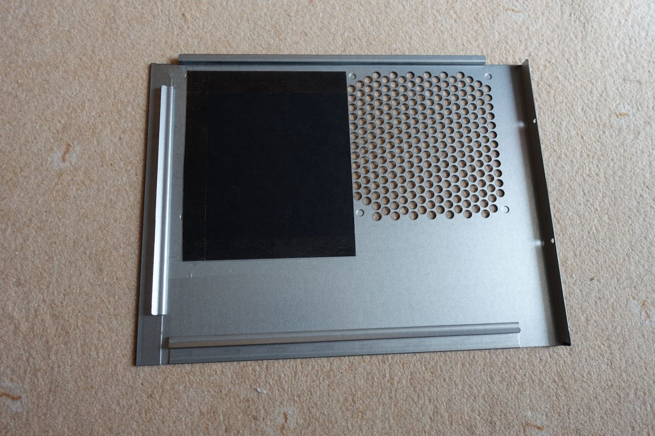
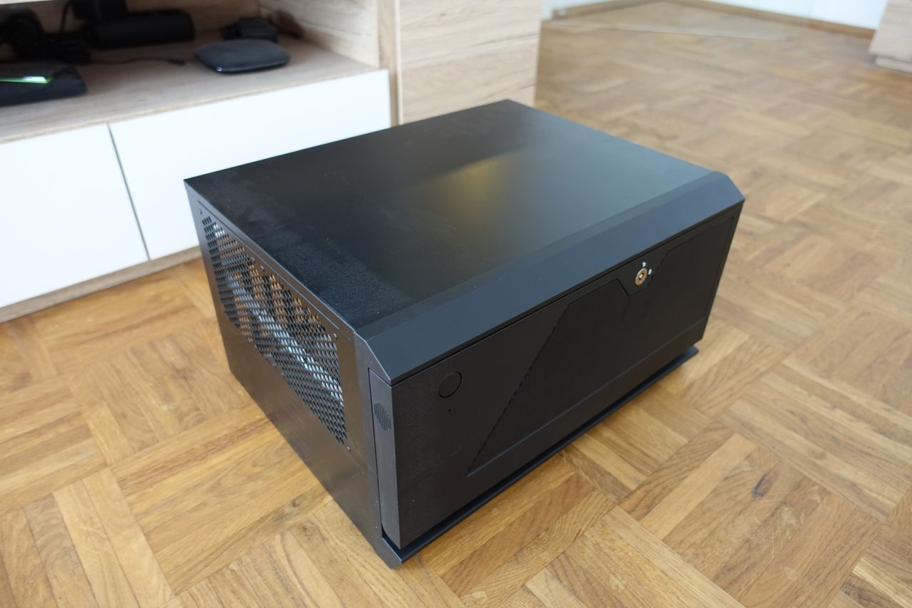
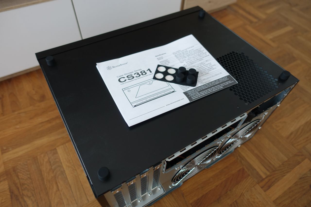
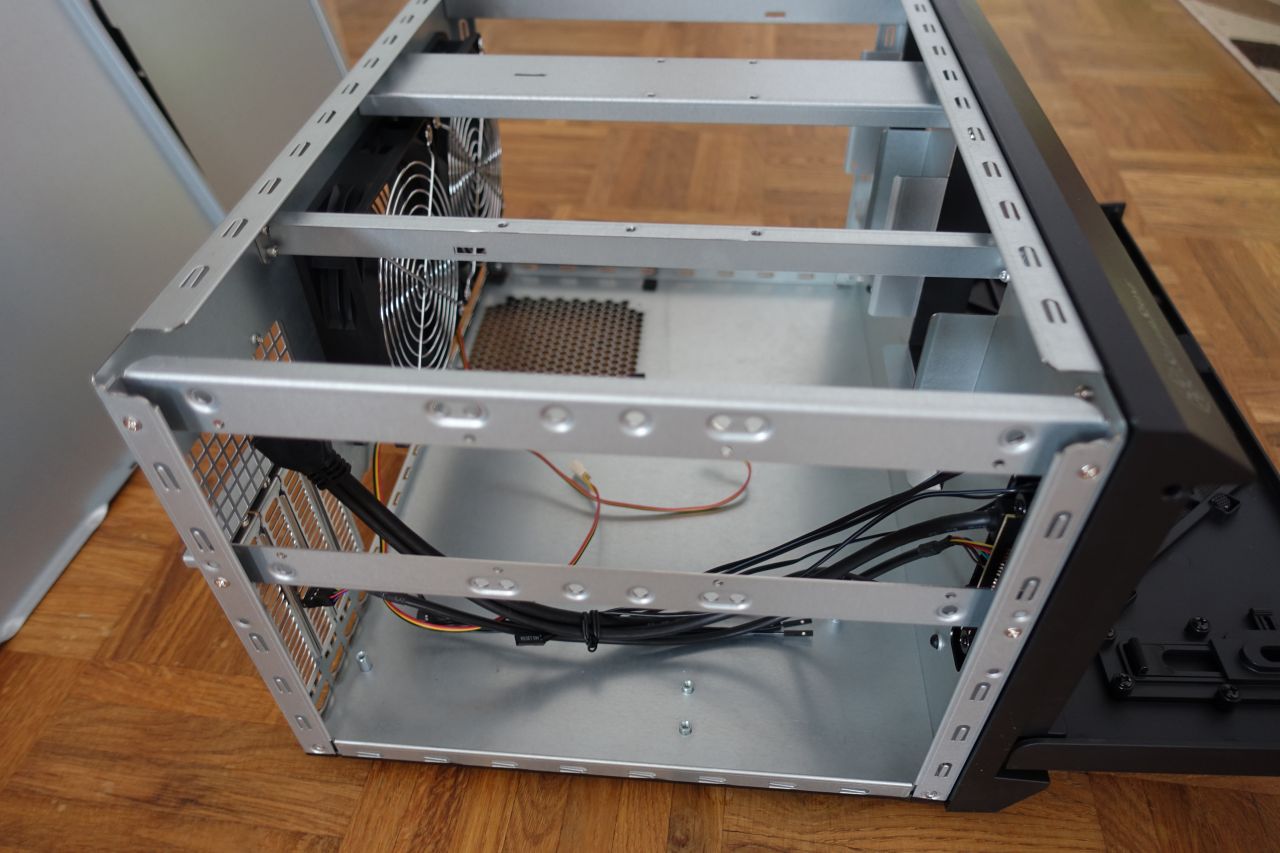
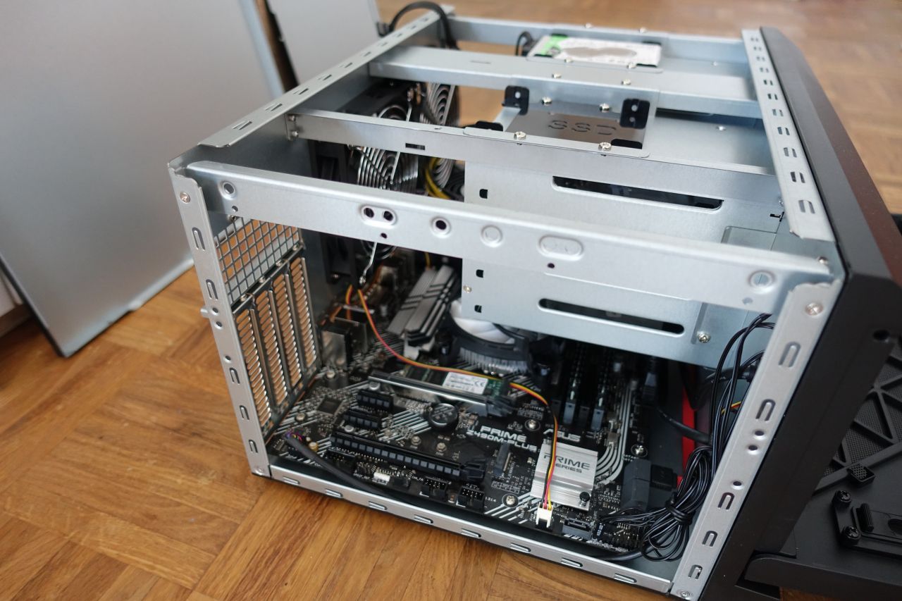
2.1. Preparing the computer case
The first task was to attach the stands to the case. They come as 8 adhesive stands in the accessory (used 4 of them), the case can stand either in the “desktop” or the “tower” position (I’ll be using it in the desktop position).
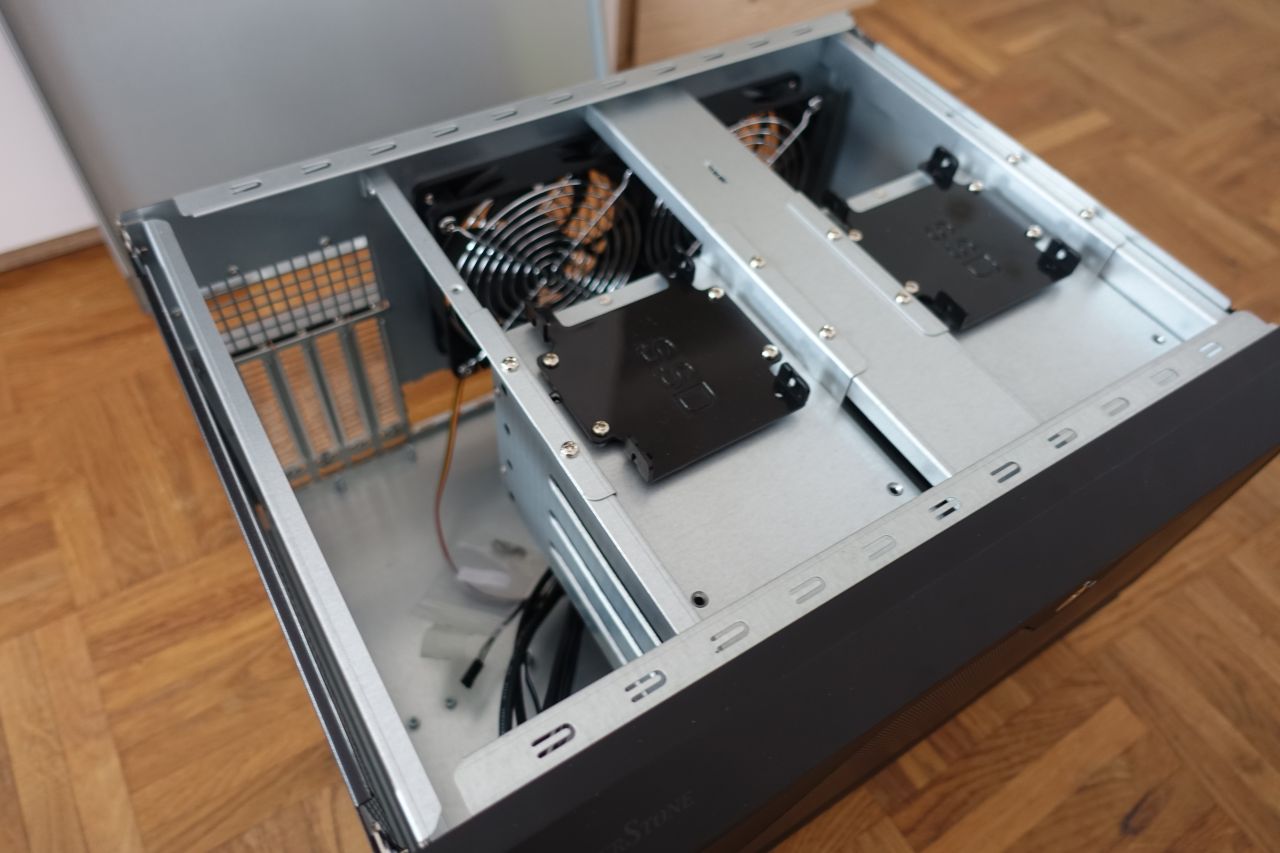
To ease the further work, the top and side covers, the rear ventilators and the HDD cages were removed:
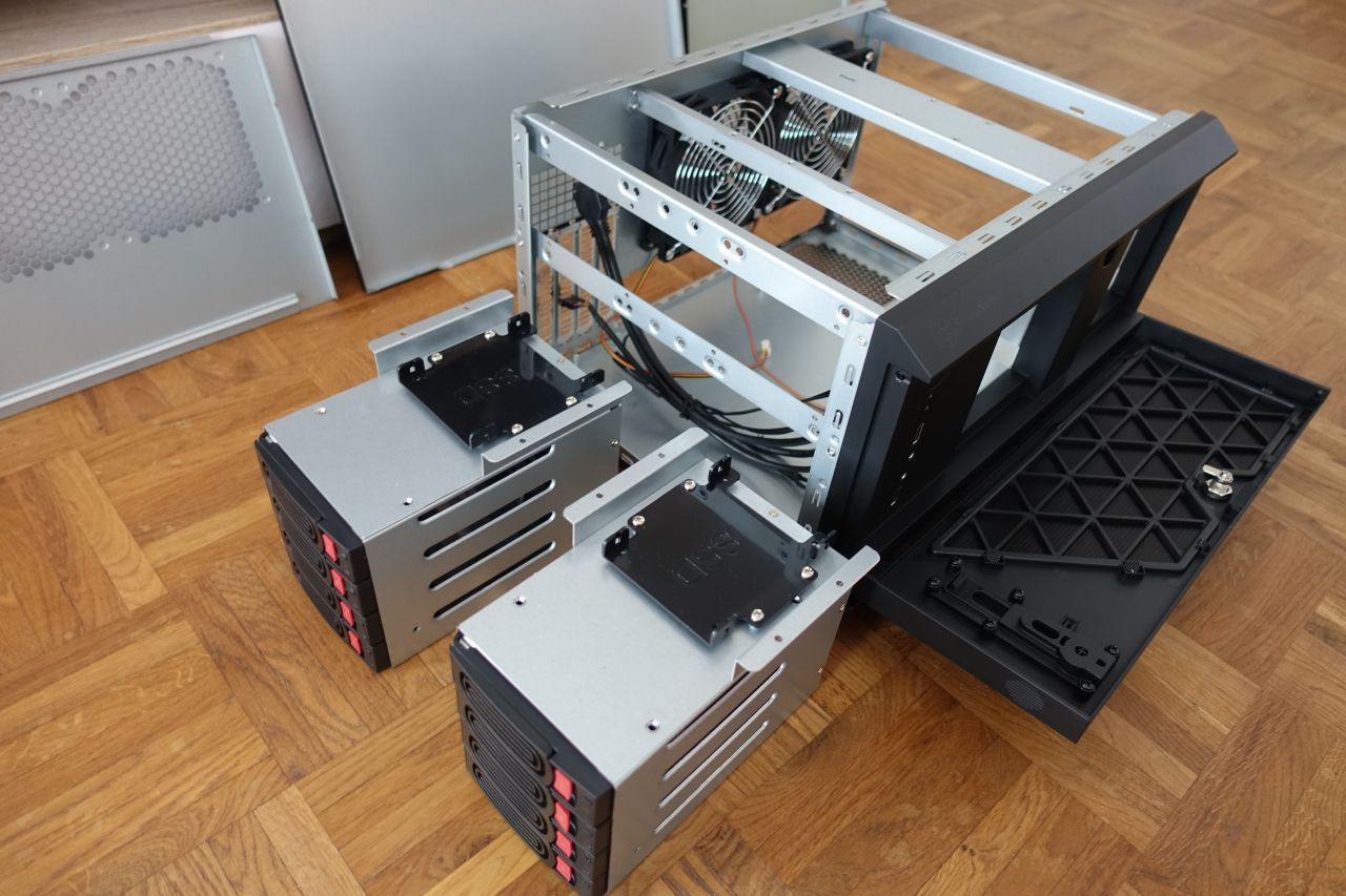
Then there should be enough room for putting all the parts in.
2.2. The motherboard
Before mounting the motherboard the IO plate needs to be inserted into the back of the case, so that the motherboard backside connectors fit in. This is simply done by carefully pushing it into the back side opening from the inside of the case (maintaining the proper orientation, obviously).
One more motherboard standoff had to be mounted, as it was missing under one of the motherboard screw holes - the micro-ATX board holes are quite standardized, but there can be some differences so one of the stands wasn’t mounted initially (they are part of the case accessories).
Important remark (CPU Cooler):
- Initially I was using the Arctic Alpine 12 LP CPU cooler. This one is mounted the “standard” Intel CPU way, i.e. can be mounted after the motherboard is in place in the case (it is in the fact easier then, because there is a space below the motherboard where the CPU cooler pins go).
- However if having a CPU cooler with separate additional backplate (like the Noctua NH-L9x65 I switched to later, or most of the water cooling systems and generally heavier heatsinks), these must be mounted before inserting the motherboard into the case (otherwise you’ll be unable to mount the extra backplate).
The case front panel connectors then also need to be attached according to the motherboard manual (so that the PC can be switched on by the front panel buttons, the power and hdd leg glow, the front panel USB and audio connectors work etc.).
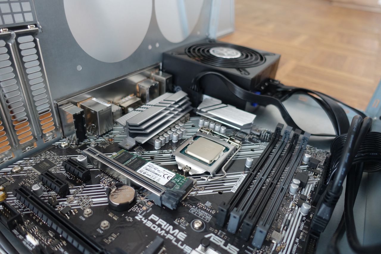
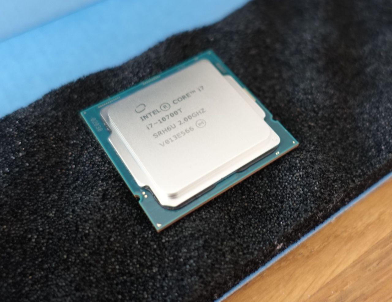
2.3. The CPU
After the MB is in place, the CPU can be inserted into the socket (if mounting the CPU heatsink with a backplate, this sometimes also needs to be done before inserting the motherboard into the case).
This is generally quite straightforward, just need to be careful to not use too much force and maintain the proper orientation (there are matching indicators for the proper alignment). First the retention arm and the bracket is opened, then the CPU can be inserted in the correct orientation (beware the indicators) and the bracket and retention arm closed.
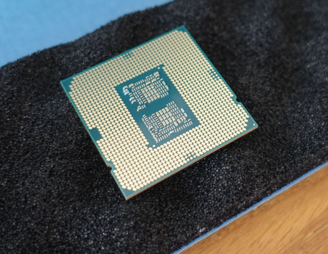
Always try to hold the CPU on the sides, never touch the bottom pins as they are really delicate and the most susceptible to static charges.
2.4. The CPU cooler
As mentioned in the motherboard part, some of the CPU coolers have a backplate and must be mounted (at least partially, the backplate must be on) before the motherboard is inserted into the case.
The thermal paste:
- there must be a thermal paste present between the CPU heatspreader (the top of the CPU) and the heatsink, otherwise the thermal transfer from the CPU to the cooler would be very poor (basically there would be air gaps and the air has a very bad thermal conductivity)
- some of the CPU coolers come with the thermal compound already pre-applied on them (like the Arctic Alpine 12 LP that I used initially, which has the MX-2 thermal compound already applied, or the Intel boxed coolers) - in that case *do not put any extra thermal paste on there* (you generally only want a very thin layer, just to fill the eventual air gaps, but not to have a thick thermal compound layer in between the CPU and the cooler)
- some other coolers do not have the thermal compound applied (like the Noctua NH-L9x65 that has the thermal paste packed separately), there the thermal paste must be applied onto the CPU before attaching the heatsink
- there are multiple techniques of applying the thermal paste; for the smaller CPUs like the Intel ones the easiest is to just put a drop of approx. 4 mm diameter in the middle and attach the CPU cooler, which then spreads the compound in between the CPU and the heatsink (it is actually one of the best techniques to avoid the air bubbles, as the thermal compound spreads from the middle to all directions, pushing the air out)
- see e.g. here for details and other techniques:
The Noctua NH-L9x65 has the NT-H2 thermal paste packed in, but I actually used the Arctic MX-4 I had at hand (should be just very slightly better according to the reviews, however the difference is very small and the the NT-H2 should be completely fine too).
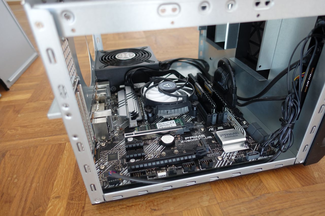
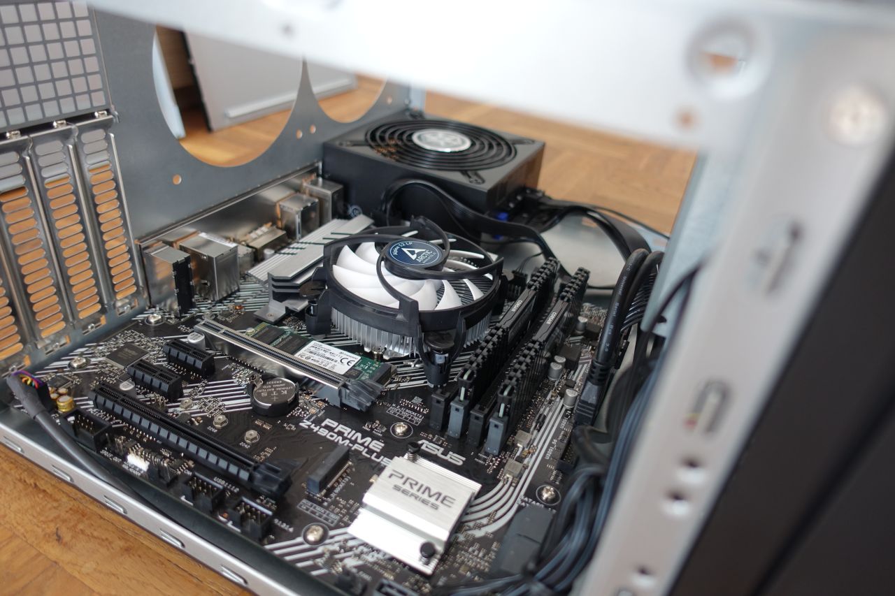
The picture shows the initial version with the Arctic Alpine 12 LP active heatsink mounted:
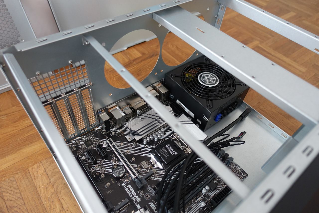
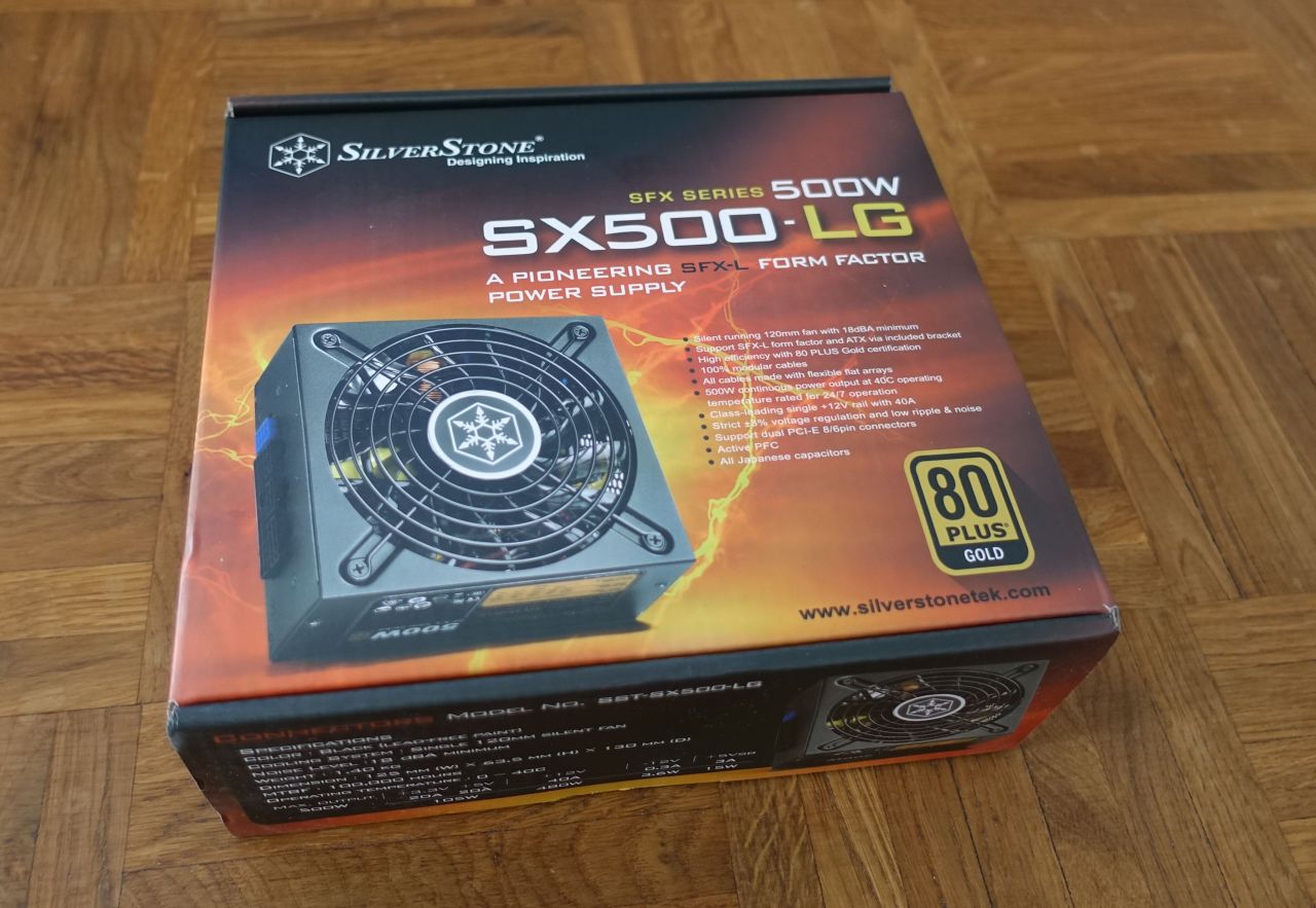
2.5. The power supply
The power supply can be mounted in 2 directions, with the ventilator either facing downwards/outwards (there are air holes under the PSU position so that the air can come in) or upwards/inwards the case.
As you could already see in the pictures above, I mounted the power supply with the ventilator facing inwards into the PC case. This orientation has both advantages and disadvantages:
- the advantage is that it additionally pulls the air through the case, helping with the airflow (“for free”, as it will turn anyway)
- the disadvantage is that if the air in the case is too hot and the power supply operates close to its limits, it may then be difficult for the PSU to cool itself properly; however that is not the concern here - as you can see later in the measurements part, the power supply operates hardly on 30% of its maximum output, so it is quite overpowered for this build and can handle being turned inwards without any issues
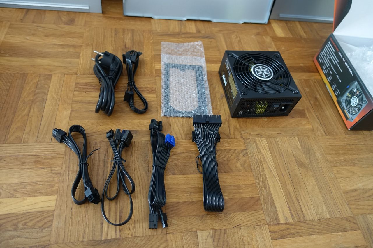
The modular power supply has the advantage that only the currently used cables can be connected, so as you can see on the pictures initially only the motherboard ATX connector and the CPU 8-pin connector are used.
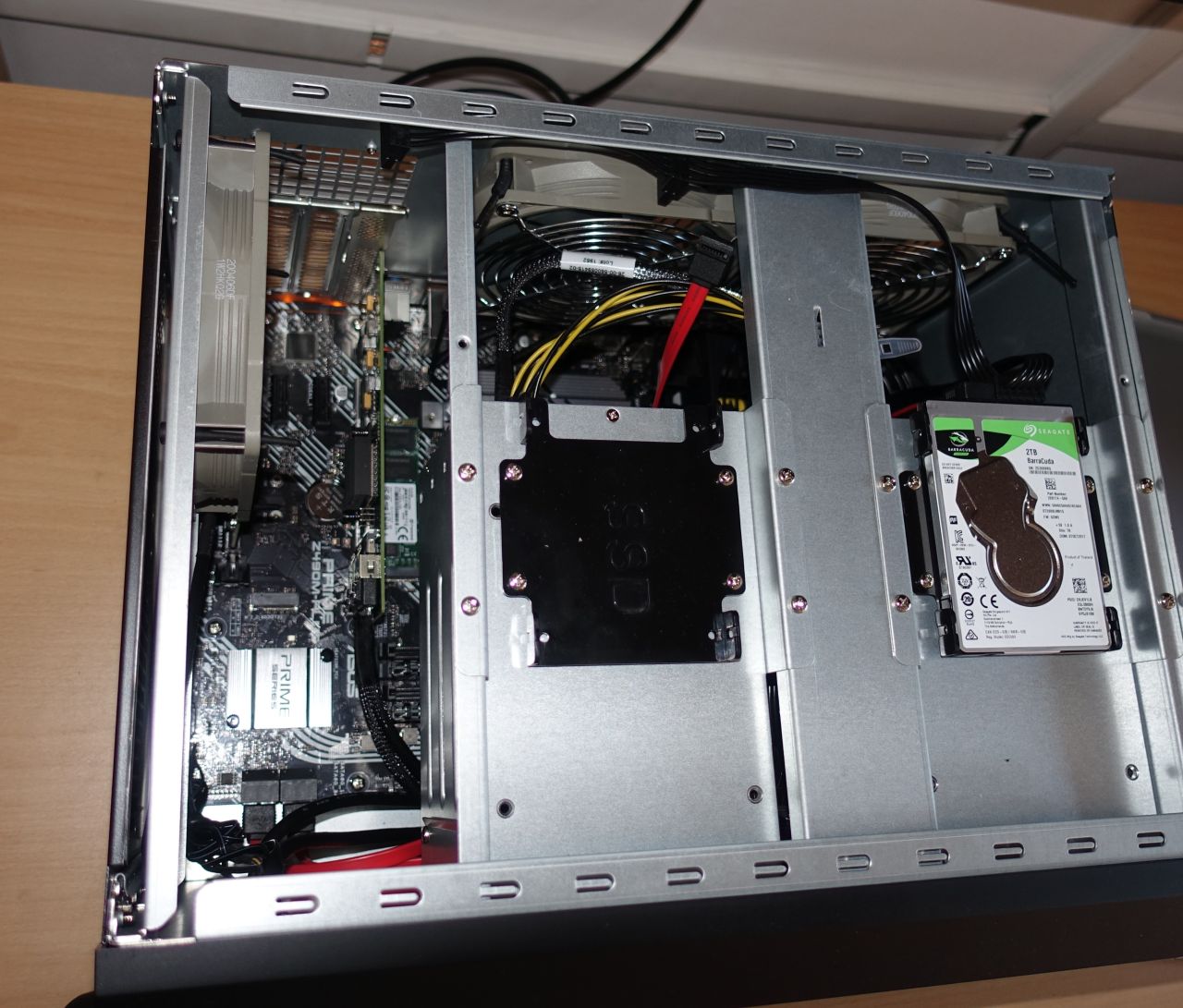
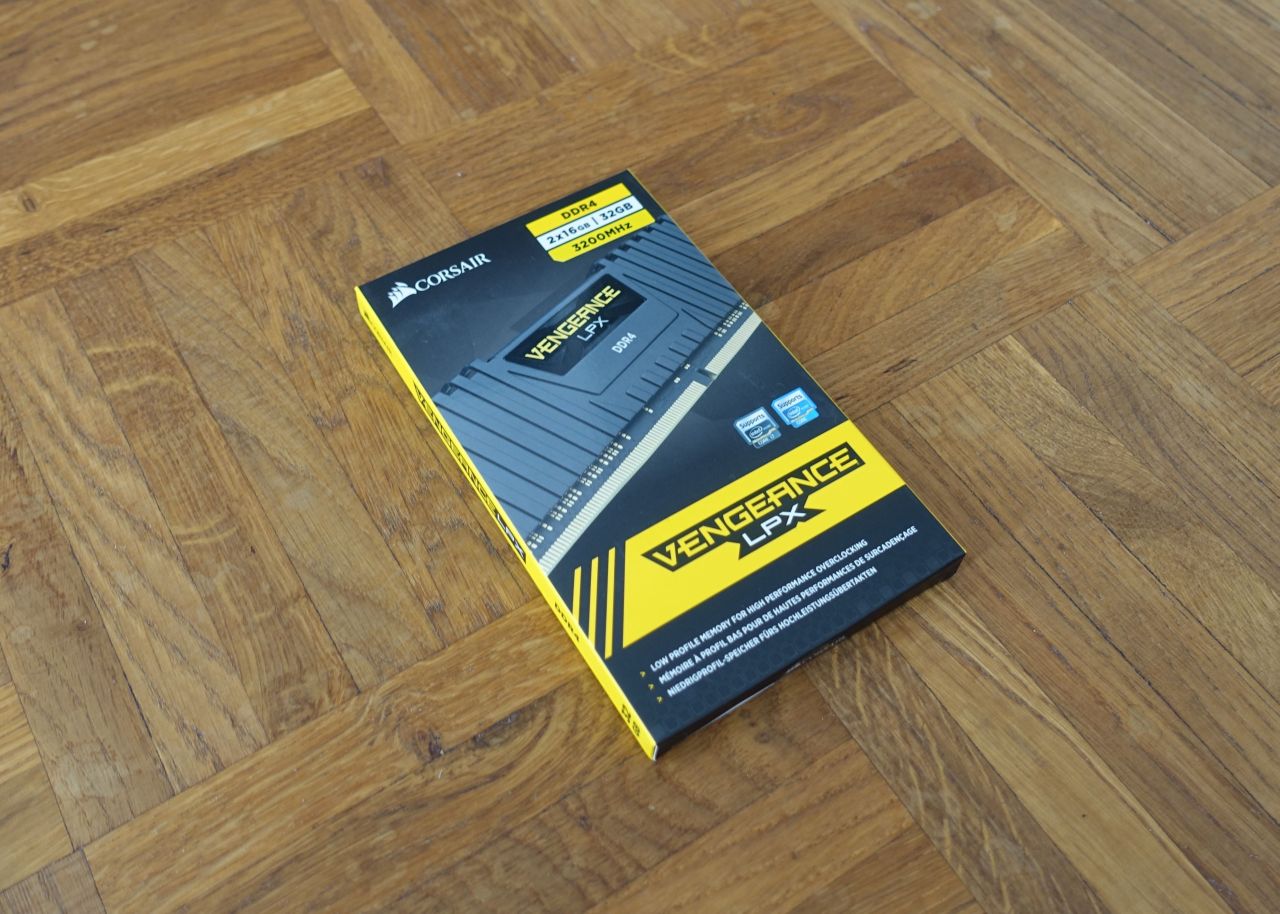
2.6. The RAM and the NVME SSD
The Transcend 512GB PCIe NVME SSD can be already seen in the above pictures. It is pretty straightforward to put it in (the matching screws are to be found in the motherboard box).
The RAM modules are used in the dual-channel configuration as recommended by the motherboard manual (you can notice that they are inserted with one empty slot in between). They also need to be inserted in the right direction - there is a key around the middle which doesn’t allow to insert them wrong (of course except when using an excessive force, which would destroy the slot and/or the module).
2.7. Initial test
After having the CPU and RAM in, and the power supply connected to the motherboard, the PC can be connected to the power (and a display via HDMI cable) and tested to see if it switches on. If it shows something on the screen, and eventually the BIOS can be entered, that is a good sign that everything is good so far.
Performing this early testing is generally recommended, because it proves that the most basic parts work. If something doesn’t work now, it would be either a bad motherboard or a bad CPU (or a RAM module, but those can eventually also be tested one-by-one separately). Each other part added later can be removed to see if that is the one causing the issues, but the motherboard, the CPU and a RAM module are the very basic parts that must all be OK otherwise nothing will work.
Eventually there might also be a power supply issue, but it is usually easier/cheaper to test a different power supply than to test a different motherboard/CPU - a different power supply could also be taken from another desktop PC you might have at home, because they are mostly compatible across all PCs nowadays, contrary to CPUs and motherboards because of the different CPU slots.
If it doesn’t turn on now, the first thing to check is to make sure that the additional CPU 8-pin power connector is attached (it is easy to forget that one and the CPU usually doesn’t start without it).
When done with the initial test, the power plug must be disconnected again to continue.
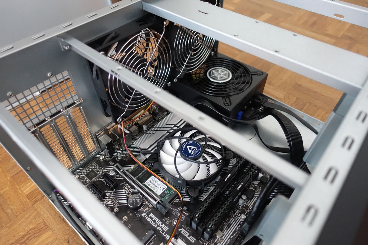
2.8. The ventilators and airflow
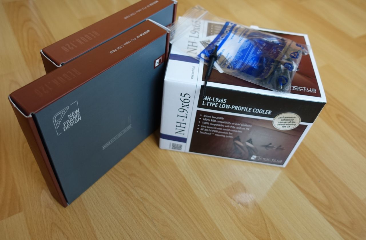
As mentioned in the first part, I eventually used the Noctua PWM ventilators:
- 2 x Noctua NF-P12 redux-1300 PWM: 300-1300 RPM
- 1 x Noctua NF-P12 redux-1700 PWM: 450-1700 RPM
The faster one (1700 RPM max) is used behind the CPU (i.e. in the middle) and connected to the CPU fan connector, so it serves as a de-facto CPU ventilator (as mentioned, after I switched to the Noctua NH-L9x65 I didn’t use its ventilator and installed it just in the passive mode, so the faster rear ventilator pulls the air off it).
The slower versions are used in the other rear position and on the side.
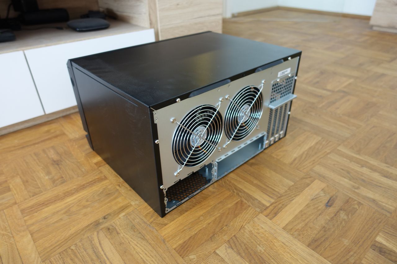
The SilverStone case recommended airflow is that the rear fans are pulling the air out and the side ventilators push in, as shown on the following picture:
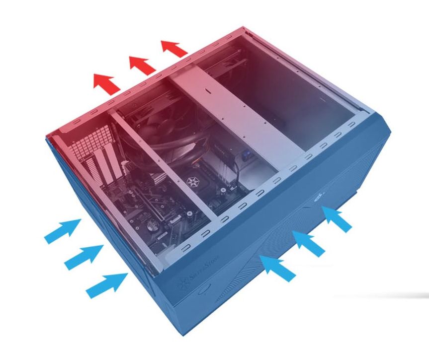
However the HDD cages are not cooled very well in that configuration, because there is not much air pulled through them (they have quite big airflow resistance, and the side fan worsens that by pushing even more air from the side).
When measuring the HDD temperatures, I found out that they are significantly lower if all the ventilators are pulling the air out, which forces more air to come through the HDD cages.
So the final configuration looks like this:
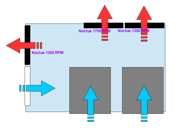
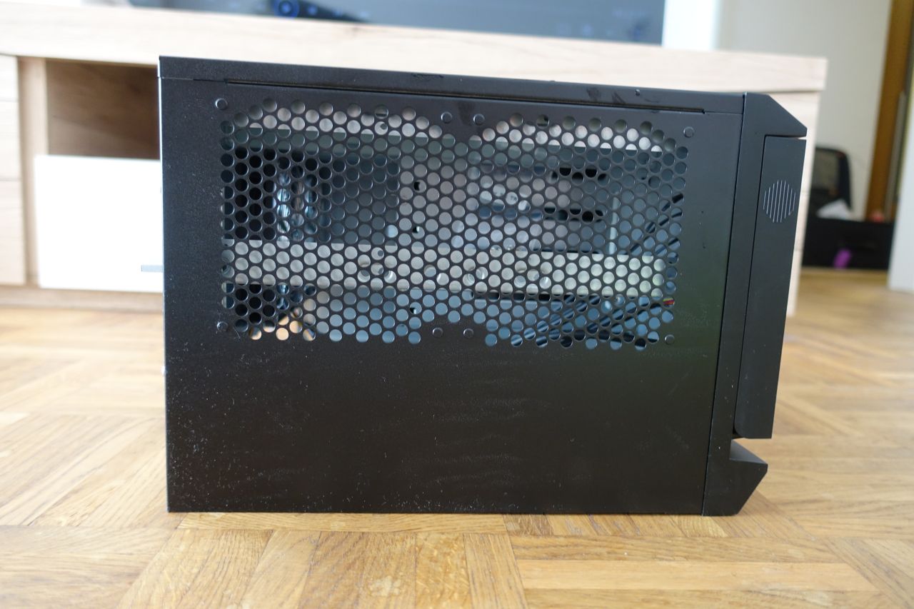
You can notice that there is still the cold air coming in through the second empty fan position. I was actually trying to put a blind over it first to force the air to come only around the HDD cages:
However I found out that it worsens the CPU temperatures rather bad, while not improving the HDD temperatures a lot, so I removed it again.
2.9. The HBA and NIC cards
The 10GTek LSI-2008-8I HBA and the I350-T4 cards need to be inserted into the PCI-Express slots. The long x16 slots need to be used for the x8 and x4 cards.
2.10. The remaining cabling
Now most of the work is done so the remaining cabling can be connected and prepared for use.
There were a few more cables and connectors to attach:
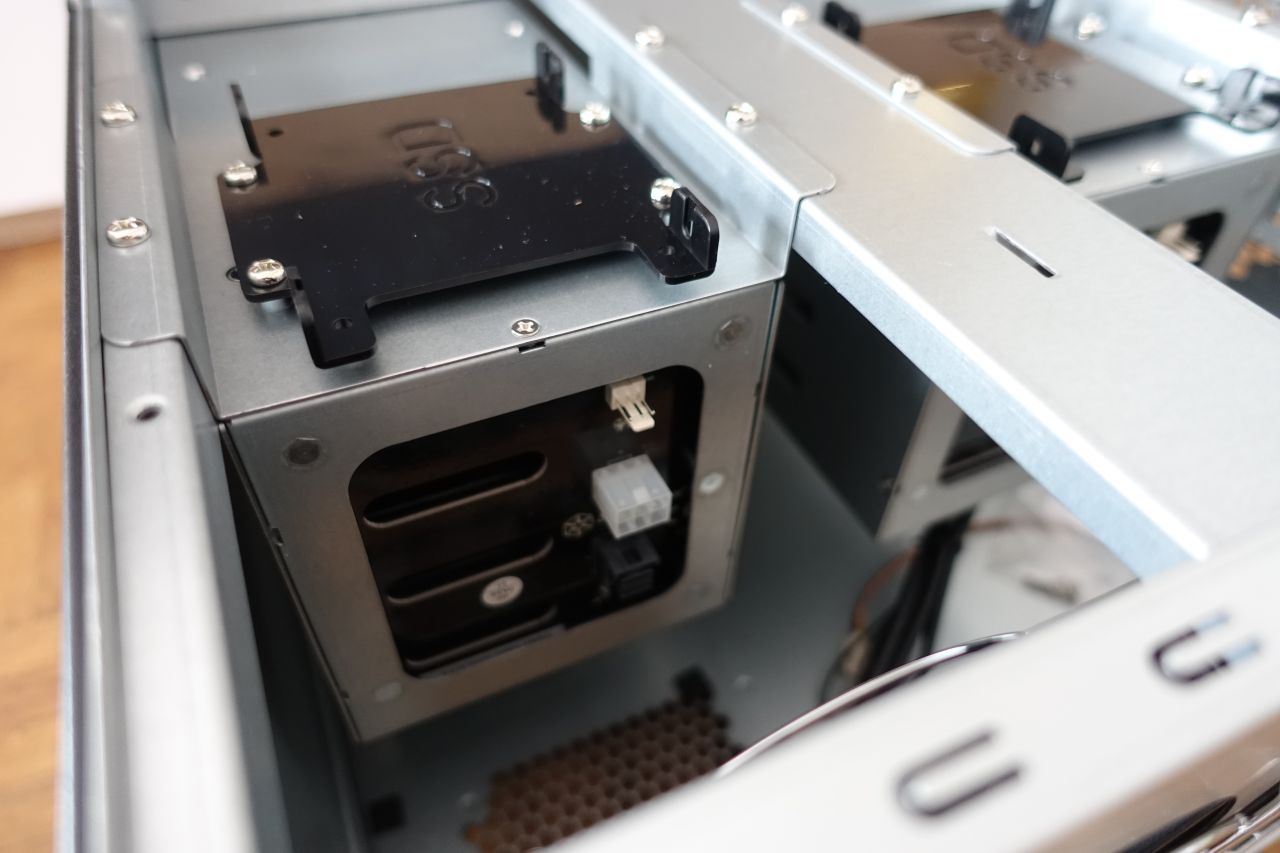
- the SATA power cable
- the PCIe power cable - used to power the HDD cages (the case accessory contains a splitter cable from PCIe 8-pin to 2x PCIe 6-pin connectors)
- the SATA data cables to the motherboard (for the extra SATA drives that will go on top of the HDD cages)
- the HBA SAS cables (SFF-8087 to SFF8643) into the HBA card
The cables can be hidden under and between the HDD cages nicely, eventually bound together and attached to the brace on top of the case (for the cables going to the HDD cages).
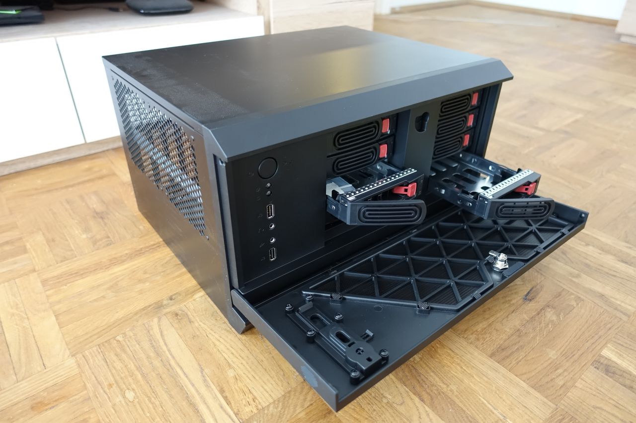
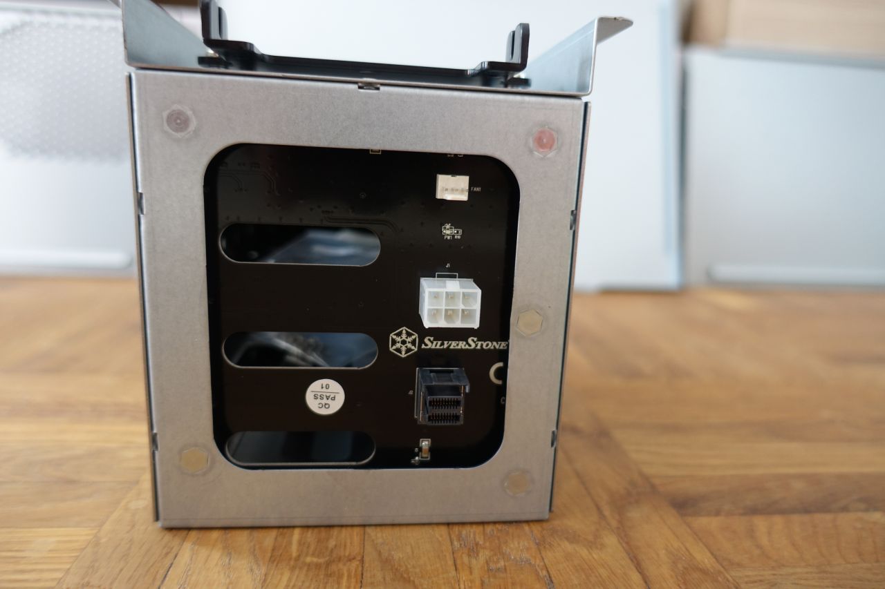
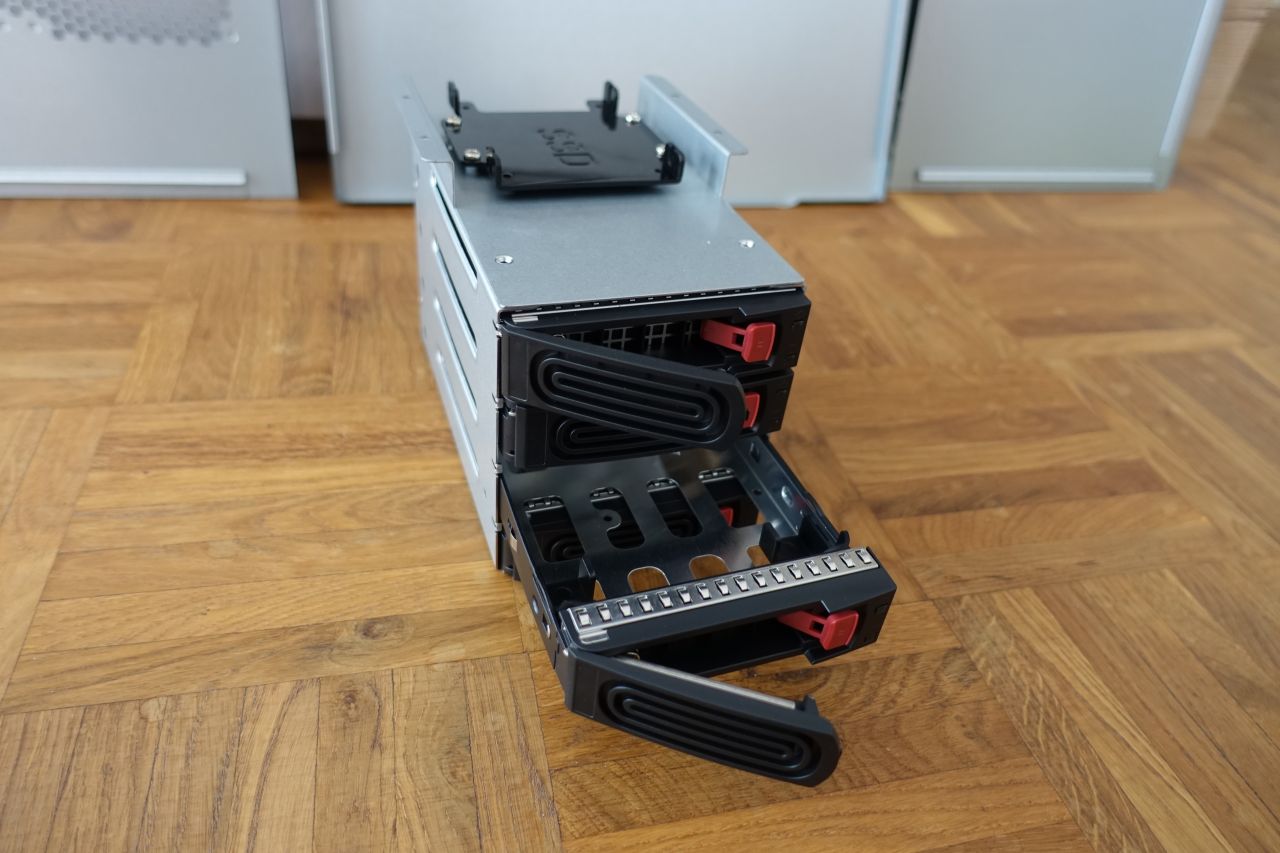
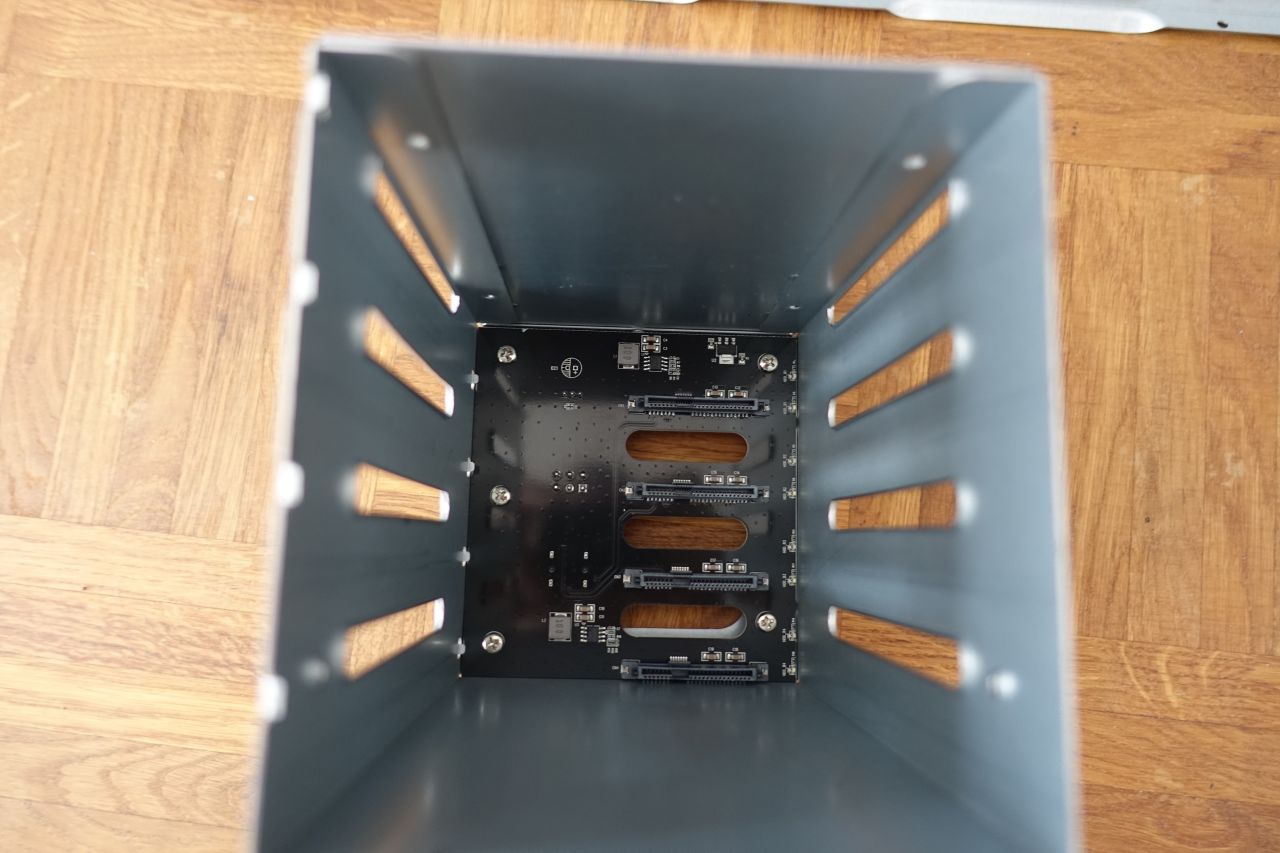
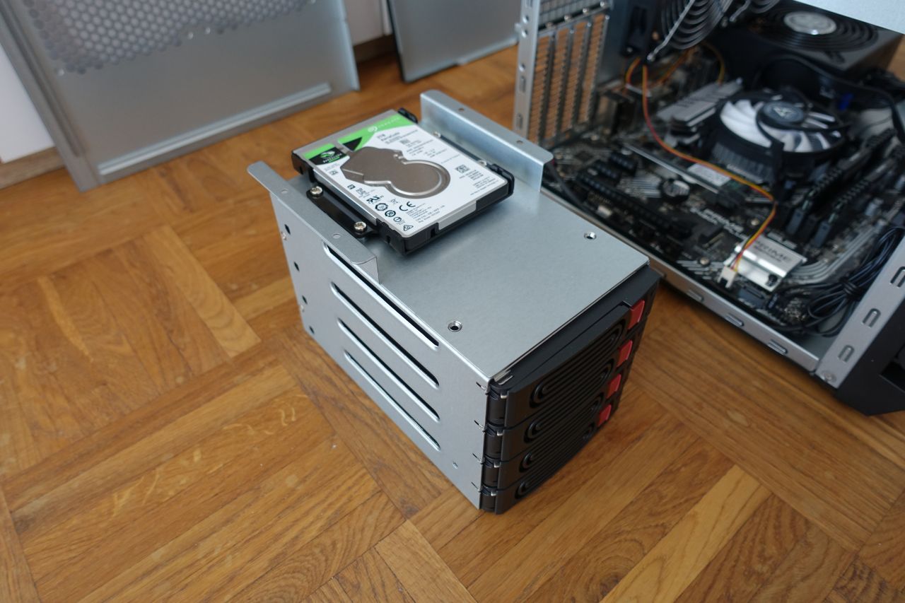
2.11. The HDD cages
The HDD cages are the last thing to put back in to complete the machine. They are then connected to the PCIe power cables and the SFF-8643 data cable connectors. Also if there are any extra 2.5” HDD/SSD, they need to be connected to the SATA power and data cables.
After that the side and top panels can be put back and we are done.
HDD cage device assignment order
In the Ubuntu the disks in the cage are assigned like this:
| Left Bay | Right Bay |
|---|---|
| /dev/sde | /dev/sda |
| /dev/sdg | /dev/sdc |
| /dev/sdh | /dev/sdd |
| /dev/sdf | /dev/sdb |
(the Left / Right bay positions can be switched depending on how the cables are connected to the HBA card connectors)
The ‘/dev’ mapping assignment can also shift depending on where the disks are inserted / removed.
Therefore it is strongly recommended to identify the disks according to the disk ID (‘/dev/disk/by-id’) or path (‘/dev/disk/by-path’) instead of the “standard” device IDs. Especially for the stripped RAID configurations (RAID-5/6) where changing the disk designators when a single disk is removed (/ failed) can cause the array to fail.
3. Testing and measurements
I was measuring the temperatures under Ubuntu Linux as described in each section.
All the commands are to be run with the administrator permissions.
To not have to repeat “sudo” every time, it is recommended to enter the admin console for the task:
sudo -i
In particular it is not entirely necessary to install the OS to do the measurements, as that can be done as well by using a live bootable USB, for example the Ubuntu Live USB.
However if running off the Ubuntu Live Desktop, the “apt” data sources need to be updated (as the Live Desktop is missing the ones needed for installing the tools):
# list the existing sources
cat /etc/apt/sources.list

# add the "universe" sources
# - use the same distribution name as listed, for example "focal"
echo "deb http://archive.ubuntu.com/ubuntu/ focal universe" \
    >> /etc/apt/sources.list
echo "deb http://archive.ubuntu.com/ubuntu/ focal-updates universe" \
    >> /etc/apt/sources.list

# update the apt database
apt update
3.1. The CPU temperatures
The CPU temperatures were measured by the Ubuntu “sensors” command.
The installation and usage:
# install the sensors package
apt install -y lm-sensors

# run the sensors auto-detection
sensors-detect --auto

# show the sensor values
sensors
Another tool that shows the CPU temperatures in real-time is the “i7z” (it is handy to be able to watch the temperatures changing):
# install the package
apt install -y i7z

# run the tool
i7z
For stress-testing the CPU the “stress” tool has been used:
# install the package
apt install -y stress

# run the stress test (16 threads, 10 min)
stress --cpu 16 --timeout 600
(the timeout is specified in seconds, i.e. the value of “600” means 10 mins)
a) using the initial Arctic Alpine 12 LP CPU cooler:
Unfortunately I didn’t measure the stress test with the active Arctic cooler, I only started measuring them after the CPU cooler was replaced.
Without the side ventilator, idle:
Adapter: ACPI interface
temp1: +27.8°C (crit = +119.0°C)

coretemp-isa-0000
Adapter: ISA adapter
Package id 0: +37.0°C (high = +80.0°C, crit = +100.0°C)
Core 0: +35.0°C (high = +80.0°C, crit = +100.0°C)
Core 1: +35.0°C (high = +80.0°C, crit = +100.0°C)
Core 2: +35.0°C (high = +80.0°C, crit = +100.0°C)
Core 3: +33.0°C (high = +80.0°C, crit = +100.0°C)
Core 4: +34.0°C (high = +80.0°C, crit = +100.0°C)
Core 5: +33.0°C (high = +80.0°C, crit = +100.0°C)
Core 6: +34.0°C (high = +80.0°C, crit = +100.0°C)
Core 7: +34.0°C (high = +80.0°C, crit = +100.0°C)

i350bb-pci-0500
Adapter: PCI adapter
loc1: +50.0°C (high = +120.0°C, crit = +110.0°C)
With the side ventilator (pulling outwards):
Adapter: ACPI interface
temp1: +27.8°C (crit = +119.0°C)

coretemp-isa-0000
Adapter: ISA adapter
Package id 0: +36.0°C (high = +80.0°C, crit = +100.0°C)
Core 0: +33.0°C (high = +80.0°C, crit = +100.0°C)
Core 1: +34.0°C (high = +80.0°C, crit = +100.0°C)
Core 2: +34.0°C (high = +80.0°C, crit = +100.0°C)
Core 3: +33.0°C (high = +80.0°C, crit = +100.0°C)
Core 4: +32.0°C (high = +80.0°C, crit = +100.0°C)
Core 5: +32.0°C (high = +80.0°C, crit = +100.0°C)
Core 6: +32.0°C (high = +80.0°C, crit = +100.0°C)
Core 7: +33.0°C (high = +80.0°C, crit = +100.0°C)

i350bb-pci-0500
Adapter: PCI adapter
loc1: +47.0°C (high = +120.0°C, crit = +110.0°C)
b) after replacing by the Noctua NH-L9x65 as semi-passive (original case ventilators):
These measurements are all with the side ventilator mounted.
Idle (stabilized after 15 mins):
Adapter: ACPI interface
temp1: +27.8°C (crit = +119.0°C)

coretemp-isa-0000
Adapter: ISA adapter
Package id 0: +45.0°C (high = +80.0°C, crit = +100.0°C)
Core 0: +43.0°C (high = +80.0°C, crit = +100.0°C)
Core 1: +43.0°C (high = +80.0°C, crit = +100.0°C)
Core 2: +43.0°C (high = +80.0°C, crit = +100.0°C)
Core 3: +42.0°C (high = +80.0°C, crit = +100.0°C)
Core 4: +42.0°C (high = +80.0°C, crit = +100.0°C)
Core 5: +41.0°C (high = +80.0°C, crit = +100.0°C)
Core 6: +42.0°C (high = +80.0°C, crit = +100.0°C)
Core 7: +42.0°C (high = +80.0°C, crit = +100.0°C)

i350bb-pci-0500
Adapter: PCI adapter
loc1: +47.0°C (high = +120.0°C, crit = +110.0°C)
Stress (stabilized after 15 mins):
Adapter: ACPI interface
temp1: +27.8°C (crit = +119.0°C)

coretemp-isa-0000
Adapter: ISA adapter
Package id 0: +83°C (high = +80.0°C, crit = +100.0°C)
Core 0: +82.0°C (high = +80.0°C, crit = +100.0°C)
Core 1: +82.0°C (high = +80.0°C, crit = +100.0°C)
Core 2: +81.0°C (high = +80.0°C, crit = +100.0°C)
Core 3: +82.0°C (high = +80.0°C, crit = +100.0°C)
Core 4: +81.0°C (high = +80.0°C, crit = +100.0°C)
Core 5: +82.0°C (high = +80.0°C, crit = +100.0°C)
Core 6: +82.0°C (high = +80.0°C, crit = +100.0°C)
Core 7: +82.0°C (high = +80.0°C, crit = +100.0°C)

i350bb-pci-0500
Adapter: PCI adapter
loc1: +44.0°C (high = +120.0°C, crit = +110.0°C)
Here the idle temperatures went about 10 degrees Celsius up compared to the active cooling. However they are still completely fine (45 degrees is no issue for the CPU).
The maximum measured temperatures are quite high, but still not reaching close to the maximum of 100 degrees where the CPU would start throttling down.
c) the Noctua NH-L9x65 semi-passive in the final configuration:
The middle rear ventilator 450-1700 RPM connected to the CPU fan connector, the other 300-1300 RPM ventilators in the rear right and on the side, both pulling the air out the case.
Idle (stabilized after 15 mins):
Adapter: ACPI interface
temp1: +27.8°C (crit = +119.0°C)

coretemp-isa-0000
Adapter: ISA adapter
Package id 0: +41.0°C (high = +80.0°C, crit = +100.0°C)
Core 0: +41.0°C (high = +80.0°C, crit = +100.0°C)
Core 1: +40.0°C (high = +80.0°C, crit = +100.0°C)
Core 2: +39.0°C (high = +80.0°C, crit = +100.0°C)
Core 3: +38.0°C (high = +80.0°C, crit = +100.0°C)
Core 4: +39.0°C (high = +80.0°C, crit = +100.0°C)
Core 5: +37.0°C (high = +80.0°C, crit = +100.0°C)
Core 6: +39.0°C (high = +80.0°C, crit = +100.0°C)
Core 7: +39.0°C (high = +80.0°C, crit = +100.0°C)

i350bb-pci-0500
Adapter: PCI adapter
loc1: +46.0°C (high = +120.0°C, crit = +110.0°C)
Stress (stabilized after 15 mins):
Adapter: ACPI interface
temp1: +27.8°C (crit = +119.0°C)

coretemp-isa-0000
Adapter: ISA adapter
Package id 0: +79.0°C (high = +80.0°C, crit = +100.0°C)
Core 0: +78.0°C (high = +80.0°C, crit = +100.0°C)
Core 1: +79.0°C (high = +80.0°C, crit = +100.0°C)
Core 2: +79.0°C (high = +80.0°C, crit = +100.0°C)
Core 3: +78.0°C (high = +80.0°C, crit = +100.0°C)
Core 4: +79.0°C (high = +80.0°C, crit = +100.0°C)
Core 5: +77.0°C (high = +80.0°C, crit = +100.0°C)
Core 6: +79.0°C (high = +80.0°C, crit = +100.0°C)
Core 7: +78.0°C (high = +80.0°C, crit = +100.0°C)

i350bb-pci-0500
Adapter: PCI adapter
loc1: +45.0°C (high = +120.0°C, crit = +110.0°C)
The idle temperatures went back down approx. 5 degrees in idle (so being only 5 degrees worse than the active cooler), and the stress temperatures also went down appr. 4 degrees, just below the 80 degrees mark.
So as you can see, the semi-passive cooling is somewhat at the borderline, and it would likely not be able to cope with any less efficient CPUs like the 65 W “regular” Comet Lake models (at least not in the full throttle).
But for this configuration it works reasonably well, as the noise was also a concern and the machine is very silent when in idle (of course the fans start turning faster when the CPU is stressed, but the noise is still quite fine - for comparison, my laptop is significantly louder when the hamsters are too busy).
3.2. The HDD temperatures
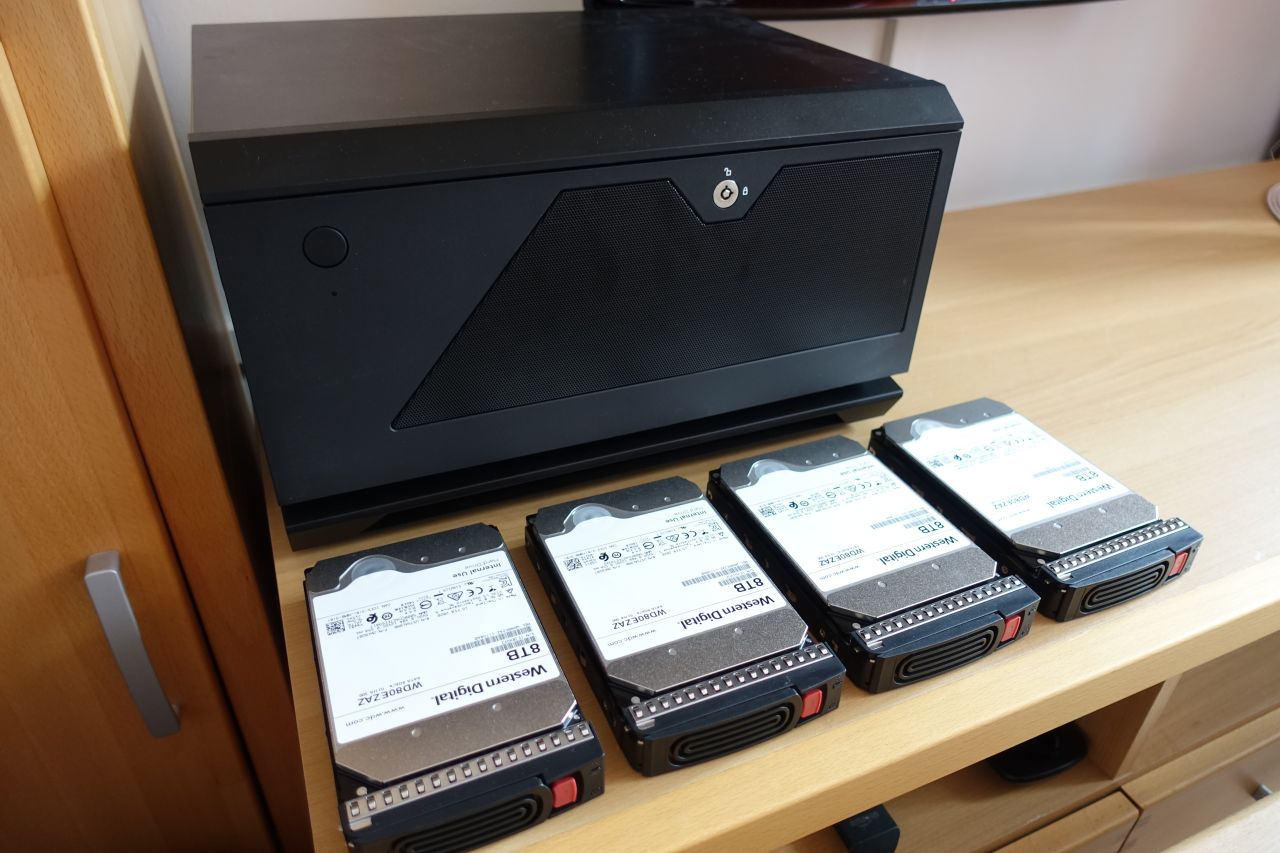
The HDD temperatures were measured with the 4x 8TB disks inserted all into the right-side HDD cage, the cage in the middle o the box was empty (just the HDD frames were in).
Used the “hddtemp” to check the temperatures:
# install the package
apt install -y hddtemp

# show the temperatures of the disks sda to sde
hddtemp /dev/sd[abcde]
I was measuring just the idle temperatures so far (left the server idling for about 1 hour and then checking the temps).
a) without the side ventilator (just the original rear ones + power supply):
/dev/sda: WDC WD80EZAZ-11TDBA0: 42°C
/dev/sdb: WDC WD80EZAZ-11TDBA0: 44°C
/dev/sdc: WDC WD80EZAZ-11TDBA0: 47°C
/dev/sdd: WDC WD80EZAZ-11TDBA0: 46°C
/dev/sde: ST2000LM015-2E8174: 33°C
These temperatures are pretty high for HDDs, especially when idle.
The ‘/dev/sda’..’sdd’ are the ones in the cage, while the ‘/dev/sde’ is the smaller one mounted on the top of the cage, just for comparison.
You can notice that the sdc and sdd temperatures are especially high; this is these disks are in the middle of the cage because of the Ubuntu disk device assignment order.
b) with the side ventilator pushing in (the SilverStone recommendation):
/dev/sda: WDC WD80EZAZ-11TDBA0: 43°C
/dev/sdb: WDC WD80EZAZ-11TDBA0: 46°C
/dev/sdc: WDC WD80EZAZ-11TDBA0: 49°C
/dev/sdd: WDC WD80EZAZ-11TDBA0: 48°C
/dev/sde: ST2000LM015-2E8174: 32°C
You can see that the HDD temperatures are even worse. That is probably because there is more air pushed from the side, therefore less air going through the HDD cages.
c) with the side ventilator pulling out (still the original ventilators + one DC Noctua NF-P12 on the side):
/dev/sda: WDC WD80EZAZ-11TDBA0: 40°C
/dev/sdb: WDC WD80EZAZ-11TDBA0: 42°C
/dev/sdc: WDC WD80EZAZ-11TDBA0: 44°C
/dev/sdd: WDC WD80EZAZ-11TDBA0: 43°C
/dev/sde: ST2000LM015-2E8174: 31°C
This is already somewhat better (especially for the middle disks).
d) the final configuration using 3 x Noctua PWM (1300 - 1700 - 1300 RPM):
/dev/sda: WDC WD80EZAZ-11TDBA0: 37°C
/dev/sdb: WDC WD80EZAZ-11TDBA0: 39°C
/dev/sdc: WDC WD80EZAZ-11TDBA0: 40°C
/dev/sdd: WDC WD80EZAZ-11TDBA0: 39°C
/dev/sde: ST2000LM015-2E8174: 30°C
Still not entirely perfect, but already looking much better and the best I could achieve so far.
3.3. The power consumption
I measured the power consumption by using the Solight DT26 power meter I just had at home, which was connected in between the power outlet and the computer plug. This way the whole PC consumption is measured, including when turned off.
The measurements are as follows, compared to the previous QNAP TS-453 Pro NAS:
| State | Home NAS build | QNAP TS-453 Pro |
|---|---|---|
| Switched off | 4 W | 2 W |
| Idle | 59 W | 40 W |
| CPU stress (no turbo - 2700 MHz) |
88 - 94 W | N/A |
| CPU stress (turbo - 3700 MHz) |
139 W | N/A |
| Max observed (CPU stress + all disks writing) |
155 W | 80 W |
3.4. The noise
As mentioned, I was also targeting the noise, sometimes even at the expense of the temperatures, as the NAS will be running most of the time (at least during daytime) and it wouldn’t be great if too noisy.
Therefore I was replacing the stock ventilators with the PWM Noctuas (they can run slower when idle than the DC fans). The idle speeds are around 450 RPM for the slower 300-1300 Noctuas, and around 700 RPM for the CPU Fan connector attached 450-1700 Noctua. They are also mounted using the rubber anti-vibration holders (visible on some of the pictures) to further reduce the noise.
In addition there is the power supply fan, which is also very silent. There is no ventilator attached to the CPU, as it is cooled semi-passively.
The HDD cages unfortunately do not have any vibration absorbing mechanisms, so the HDDs are somewhat noisy when working, but still reasonably silent when idle.
4. Conclusion
- apparently the 500 W power supply is more than enough, running on around 30% of the available power at max
- the idle power is about 50 % higher than the old QNAP, however not too bad in the comparison, considering the performance difference
- compared to a relevant off-the-shelf configuration, the QNAP TVS-1282-i7-32G “typical operational” power consumption is specified to be around 66 W
(and its CPU is still significantly weaker) - in order to keep silent, there were some compromises made on the cooling part, so the temperatures are a bit higher because of that
(but should still maintain a reasonable range)
5. Next steps
In the next part we’ll discuss the operating and file system of the new server, the requirements and the available alternatives.
6. The gallery


Leave a comment